Strip Chart ► Hardware ► Basic ► Connectors
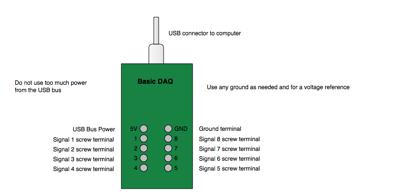
The following schematic diagrams the connectors that you will be using.
The screw connectors 1-8 correspond to the curve index in the signal window. Each connector is a single-ended connection to a digitizer. Typically, a sensor has a signal wire which can be attached to any of the signal connectors, usually in order one to eight for up to 8 sensors, a ground wire which is connected to the GND terminal and a power wire which can be connected to the USB Bus Power (5 V) connector. Make sure not to overload the power.
The Basic USB Inspector Editor attributes are pre-set for the Basic Hardware and no changes need to be made. Upon first use of the hardware make sure to click the Apply button in the inspector.
Each of the eight signal connectors is connected to only one digitizer and the 8 signals are digitized in sequence (multiplexed). Hence, if you have less than 8 signals then turn off all of the unused channels in the Basic USB Inspector Editor (de-select the switches next to the Channel Prompt Strings) and click Apply. Since less signals are multiplexed each signal that is digitized will be sampled more often and hence the effective sample rate can be increased.