Strip Chart ► Support ► Windowed Integration
The Derived Inspector Editor has many options, some are straight forward and easy, some are straight forward but require a little thought and some are not straight forward and settings may only be known a posteriori. This section shows a more advanced use, a windowed integration.
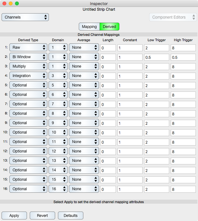
The Derived settings are shown in the figure below and each row is described below the table.
The mapping takes the voltage from channel 1, called the domain signal, and transforms it 4 times into the windowed integration, which is called the range signal.
| Row Number | Operation Type | Operand Channel | Description Of Mapping |
| 1 | Raw | 1 | This specifies to use the raw signal from the source channel one, i.e.: this is the domain value (vector, if you will) of the mapping. |
| 2 | Bi Window | 1 | This takes the operand from row one (the raw signal) and applies a threshold window to it. The result is placed in channel 2. The raw signal is assumed to start out at zero, increase and then decrease. This bi-window mapping maps that signal to zero until it reaches a value of 0.5 (high trigger) and then maps it to one until it reaches a value of 0.5 (low trigger) at which time it maps it to 0 again. Hence, the window is in the interval where the value is above 0.5. |
| 3 | Multiply With Previous | 1 | This mapping multiplies channel one (the raw signal) with the previous channel (the window) to produce a windowed representation of the raw signal. |
| 4 | Integrate | 3 | This mapping integrates the windowed representation (channel 3) thus producing the range value of the composite mapping. |
| 5-16 | Optional | N/A | These channels are set to optional, i.e.: they are not used. |
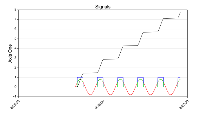
The result of the mapping specified above and each of its intermediate mappings are shown in the figure below:
| Channel Number | Curve Color | Description Of Signal |
| 1 | Red | This is the raw signal which is a cosine function offset in the y-direction by a small amount. Because of the offset in the y-direction any integration of the signal will be a sine function with a gradual increase as time goes on. |
| 2 | Blue | This is the window produce from the raw signal. |
| 3 | Green | This is the windowed raw signal. |
| 4 | Black | This is the windowed integration of the raw signal of channel one. |
With this real-time composite mapping system many different mapping capabilities are possible. You do not have to use the same function for the window and integration. For example, the window may be produced from an analog input channel hooked to a device that senses the beginning of an experiment. To a large extent, the efficacy of the derived settings is a matter of imagination.