The Simulation device can be useful to test methodology for data storage and analysis without having hardware.
The following details the Simulation parameters.
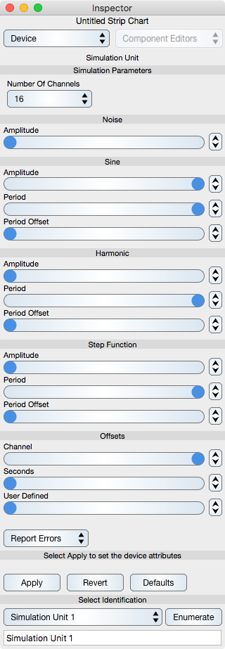
Simulation Parameters
Number Of Signals : Varies from one to sixteen. Choose a number similar to what you will use in practice.
Noise
Noise: Defines the amount of noise relative to the signal. This is very valuable for determining average and fit parameters in the Derived processing. Once you start using derivatives and feedback loops then noise plays an important role in determining algorithm selections.
Amplitude : Sets the amplitude of the noise.
Sine
Defines the sine function component defined by A sin(t (P + i * O)) where A is the amplitude, P is the period, O is the period offset, t is time and i is the channel index.
Amplitude : Amplitude and is set between 0 and 10 and equals the maximum of the sine function.
Period : P is the period and is set to one second per cycle when the slider is to the right and infinite (flat) when the slider is to the left.
Period Offset : The Period offset slider offsets the period on a per channel basis so that the period can vary per channel.
Harmonic
Defined by A (cos(t P) + sin(2 t P) + cos(3 t P) + sin(4 t P))/4.
Amplitude : The amplitude (A) and is set between 0 and 10
Period : The period (P) is set to one second per cycle when the slider is to the right and infinite (flat) when the slider is to the left.
Period Offset : The Period offset slider offsets the period on a per channel basis so that the period can vary per channel.
Step Function
Step Function Parameters: Defined by A when t is an even second and 0 when t is an odd second (excluding fraction) when the Period slider is set to the right. The alternate values are more rapid when the slider is moved left. The Period offset slider offsets the period on a per channel basis so that the period can vary per channel.
Offsets
Channel Offset: adds 10 times channel index when the slider is to the right and less offset as the slider is moved to the left. Move the slider all the way to the right to separate the signals and move the slider all the way to the left when looking at spectra so that there is no DC bias.
Seconds Offset: adds the seconds value to each signal when the slider is to the right, and a lesser amount per channel when the slider is moved to the left.
User Defined Offset: Each signal increases when the slider is moved to the right and decreases when the slider is moved to the left.