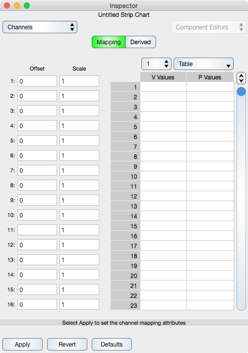
Mapping Coefficients
The offset and scale field defines a linear mapping between volts and physical units and is defined as:
physical unit = voltage * scale + offset
The channel mapping table defines an arbitrary curve between volts and physical units in terms of x y pairs. The format is like:
x1 y1

x2 y2

...

xN yN
Data points that have voltage out of the interval {x1, xN} are mapped to the respective limit constant. For example, if the voltage is less than x1 then that voltage gets mapped to the constant y1.
The linear mapping coefficients will be used if a channel mapping table for a particular channel index is not specified.
How To Derive Mapping Coefficients
To derive the mapping coefficients apply the following methodology. First measure the voltage at two known physical units values. For example, if you are measuring temperature then measure an ice cube and then body temperature. Define those values as:
v1 = voltage measured from the ice cube

v2 = voltage measured from the body

t1 = ice cube temperature (32 degrees fahrenheit)

t2 = body temperature (98.6 degrees fahrenheit)
Then the offset and scale are:
scale = (t2-t1)/(v2-v1)

offset = t1 - v1 * scale
If you wish to use the table lookup then simply enter the values as:
v1 t1

v2 t2
into the channel mapping table. But make note of the fact that voltages sampled by a probe at temperature less than that of ice (t1) get defined as ice temperature, and voltages sampled by a probe at temperature greater than body temperature get mapped to body temperature. By adding voltage and temperature pairs at lower and higher temperatures you can build up a more extensive mapping, but only need do so if your sensor is nonlinear.