Strip Chart ► Overview ► Spectra
Strip Chart implements a multi-channel time series plot on an amplitude v.s. time coordinate. Dragging the Spectrum graph to the document containing a strip chart will then show both the time series and spectrum plot simultaneously as shown below.
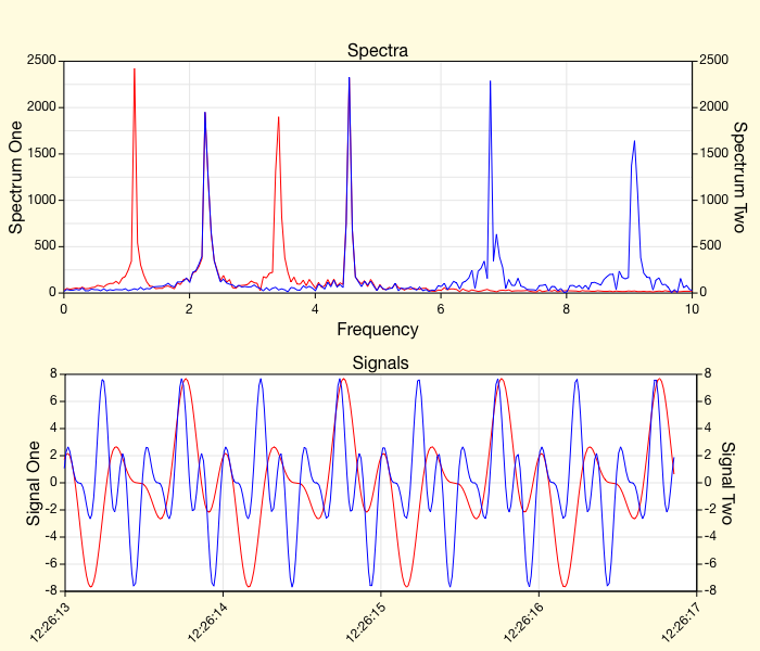
The spectral representation shows the signals transformed by a discrete Fourier transform. You can see from the plots above that the signal plot shows some periodicity in the signals, but it is the spectral plot that shows the periodic nature in a quantitative format which permits better analysis and isolation of the energy in the signals as a function of frequency. This section explains that spectral output representation.
General Description
The spectral output represents the frequency of the signals at the right hand side of the signal plot. The number of samples used to produce the spectrum for a signal is called the spectral-length. When starting acquisition you must wait for twice the spectral-length number of samples before the spectrum is computed accurately. If you use the slider to slide the signals back in time then the spectra are recomputed from the portion of the signals ending on the right hand side of the signals plot. In that sense, the spectra can be played back in time, just like the signals can. Thus the spectra output is a multi-channel frequency domain oscilloscope with playback capability. Keeping the slider all the way to the right keeps both the signals and spectra up to date.
Time Increment
The spectrum representation is converted from a uniformly sampled time signal. As such, you should either select the time sample interval and keep it fixed, or use hardware clocking which is by definition a constant time increment. Hardware clocking is preferred because it is a high sample rate method that is designed to have uniform time increment.
Time Window
The spectral plot is calculated from twice the spectral-length of samples (see Spectrum Inspector Editor to set that parameter). Hence you must run the signal for at least that amount of time (time increment times twice spectral-length) before the spectral plot is calculated with fidelity. The time samples used are always the ones at the right of the signal plot and then spectral-length number of samples back in time. That way, if you keep the time slider to the right then the signal plot will auto scroll to the most recent samples and the spectral plot will always be current.
The greater the time window selected (by changing the spectral-length) the greater the resolution of the spectral components.
Frequency Fidelity
The spectra output is implemented with a discrete Fourier transform. The output is magnitude, decibel-magnitude or phase. The output type and the number of time values used to compute the spectra are defined in the Spectrum Inspector Editor.
Define the following:
| ΔT | The time sample interval of the signal. |
| ΔF | The frequency interval of the spectral output. |
| N | The spectral output length (defined in the graph inspector editor). |
| Fmax | The maximum frequency of the spectral output. |
Then ΔF = 1/(2 N ΔT), and Fmax = N ΔF = 1/(2 ΔT). For example, if the hardware sample rate is 50,000 samples per second then ΔT = 0.00002 seconds (0.02 milliseconds) and Fmax = 25Khz. This is the Nyquist Frequency of the spectral output. Even though the Nyquist Frequency defines the maximum frequency of the discrete Fourier transform it does not define the fidelity of the frequency reconstruction. That depends on the exact signal type, but in general the maximum frequency that can be reconstructed with a good amount of fidelity is about half or 5 times less than the Nyquist Frequency. So, at 50,000 samples per second, 5 times less than the Nyquist Frequency means that the highest frequency component for a quality spectrum should be about 5Khz.
Think about sampling a sine wave. If you were to be as unfortunate as to start sampling the sine wave right at its zero value and the sample rate was exactly twice the frequency of the sine wave then your sampling would always pick up a value of zero; not exactly representative of the sine wave. By sampling 5 times faster you would sample that sine wave at a rate greater than its period and would be able to reconstruct it better.
The short of it is: If you sample at N samples per second then expect the highest frequency to be represented on the spectral output with fidelity to be 1/5th to 1/10th that in Hertz.