DAQ Plot ► Preferences ► Hardware ► Pro USB
The Pro Hardware preferences sets the state of the Pro Hardware. The following diagrams the Pro USB (Universal Serial Bus) DAQ hardware device preferences.
Identification Number
The Identification Number specifies the DAQ hardware unit to configure and use. If there is more than one DAQ hardware unit on your computer's USB bus then you need to select the correct one. Normally the identification number is a serial number printed on the DAQ device, however if it is not then select a identification number, enable hardware clocking and click the Apply button. During hardware clocking the comm LED on the device looks on all the time. Once you've associated the hardware to a identification number you should probably record the identification number on the DAQ device itself. Repeat this process for all identification numbers to identify each device. You can also use the digital channel settings and monitor them, or other input or output indicators to find the device to identification number association.
Analog Input
There are 14 channels of analog voltage input labeled from 1 to 14. Channel 15 is a temperature sensor output inside the unit and channel 16 is the unit's voltage source reading. Channels 15 and 16 can help calibrate, or refactor, signals based on environmental considerations. See the Screw Connector section below for channel index to screw terminal mapping.
Analog Input States
Each channel can be turned on or off. Turn all channels off except the ones you are using by clicking the switch next to the channel number in each row. Turning off unused channels will cause the hardware to sample faster as well as eliminate spurious channel output whose values are voltage floaters (have no potential reference) and may appear random in the output.
Important: Analog Input indexes always start at one and are sequential so if you turn off a state then higher index are moved down by one. For example: If you have only Analog Input index 3 and 6 states on then those channels are remapped to 1 and 2 and are shown on the graph as curve 1 and 2, etc. and the device appears to have only two channels (as many as are turned on). Thus if you use the Meta Device then you can multiplex pro hardware to 16 channels even though the physical number of channels is modulo 16.
Analog Input Gain
There are 14 channels of analog voltage input each with their own gain setting. The Gain controls a pre-amplification of the signal before digitization. The gain is post-decreased after the digitization so that the recorded voltage is invariant with respect to the gain setting. The gain does affect the effective resolution of the signal and as a consequence decreases the dynamic range of the channel and is especially important for low voltage (millivolt) signals. Make sure that the gain settings will not cause the voltage to amplify greater than 5 volts (the limit of the hardware input voltage). There are 8 gain settings: 1, 2, 4, 8 both unipolar (0 to 5 volts) and bipolar (-5 to 5 volts) designated by U-1, U-2, U-4, U-8, B-1, B-2, B-4, B-8 in the user interface.
| Gain Nomenclature | Description |
| U-1 | Unipolar gain of 1 (range 0 to 5 volts). |
| U-2 | Unipolar gain of 2 (range 0 to 2.5 volts). |
| U-4 | Unipolar gain of 4 (range 0 to 1.25 volts). |
| U-8 | Unipolar gain of 8 (range 0 to 0.625 volts). |
| B-1 | Bipolar gain of 1 (range -5 to 5 volts). |
| B-2 | Bipolar gain of 2 (range -2.5 to 2.5 volts). |
| B-4 | Bipolar gain of 4 (range -1.25 to 1.25 volts). |
| B-8 | Bipolar gain of 8 (range -0.625 to 0.625 volts). |
Clocking
If you choose to use the high-speed hardware clocking then the Samples per second entry is used instead of the sample interval on the main window. In addition, because it is hardware clocked the timebase increment is uniform and will not depend on the host load. Non-hardware clocked data has a timebase variability of a few percent, which is not a problem because the time at each point is recorded and is not assumed uniform anyways. Hardware clocking requires a dedicated USB device so make sure to turn off the feedback, digital and other options which can disrupt the data flow.
The Pro hardware has a limit of 50,000 samples per second. As such the Samples Per Second Per Channel times the number of analog input channels on should not exceed 50,000. For example: with one channel on the Samples Per Second Per Channel can be no greater than 50,000. With 5 channels on the Samples Per Second Per Channel can be no greater than 10,000. Other limiting factors are USB bus load and type, computer type and output state. The actual Samples Per Second obtainable may be less than the 50,000 limit.
Special Notes: There are a few limitations in streaming mode. Generally you must be aware of the following:
Always verify that streaming has reasonable efficacy before settling on a streaming configuration. Streaming efficacy will depend on your computer and USB bus hardware as well as the load you place on your computer.
Screw Connectors
Use the following Input Screw Connector Key to determine which channel goes with which screws. See Connectors for additional information.
| Channel Index | Description |
| 1-14 | AIN0 - AIN13 respectively |
| 15 | Hardware unit temperature sensor output in Kelvin |
| 16 | Hardware unit voltage source value. |
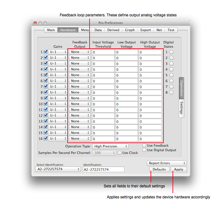
Control Loop
The Control Loop Parameters define a common feedback algorithm. Set each channel as you wish. First set the output channel, then the input voltage at which the output voltage will change. Finally set the output voltage values. The Low Output Voltage will be outputted when the input voltage is below the Input Threshold Voltage. The High Output Voltage will be outputted when the input voltage is above the Input Threshold Voltage. A common setting is 0 and 5 respectively so that when the input voltage crosses a threshold the output voltage is changed from 0 to 5 volts and can be used to activate another device.
The feedback control only occurs when the Use feedback control loop switch is selected. Special Note: If you use high-speed clocking then the feedback signals may interfere with data acquisition so you should probably not use high-speed clocking and feedback at the same time.
Digital Output
Digital controls set a low and high state of each digital output terminal. The low state is 0 volts, the high 3.3 volts. Channel 1-8 are the screw terminals FIO0-FIO7 respectively.
Reporting
The USB device can report additional information to stdout (the console). The report pop up button sets the threshold of reporting. Silent for no reporting, Error to report errors only all the way up to All, which will report errors, summary results and some state changes. If you choose Summary or above and restart the USB device then it will report the firmware version of the hardware upon restart.
Applying
No state of the hardware will change without clicking the Apply button. That is because all the states are interrelated and applying only a partial setting could put the hardware in a state where it records data in a non-nominal state. Hence, only click the Apply button when you are satisfied with all the settings.
Ethernet Settings
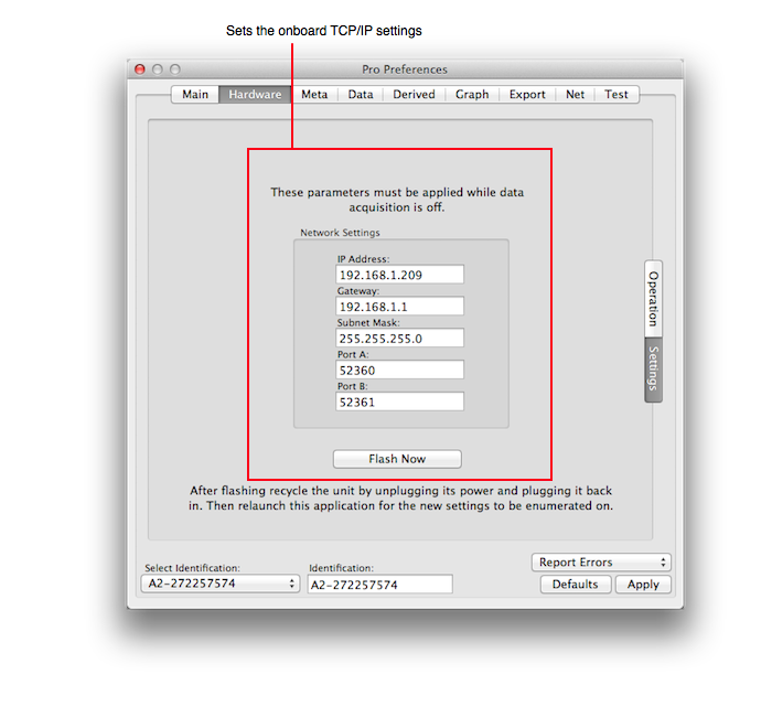
The Settings sub-pane allows the setting of the hardware's ethernet parameters. If you use the ethernet interface then make sure to synch. those settings with the Hardware References.
Important: If you use the ethernet interface for high sample rates then in Terminal apply the following commands first and then relaunch DAQ Plot.
sudo /usr/sbin/chown root:wheel "/Applications/DAQ Plot.app/Contents/MacOS/DAQ Plot"

sudo /bin/chmod u+s "/Applications/DAQ Plot.app/Contents/MacOS/DAQ Plot"
Once relaunched DAQ Plot will reduce its permissions so that it will not be a over-privileged application. If you use the USB interface then you need not perform this step.